Arduino · current
Arduino UNO R3
ATmega328P-based Arduino board with 14 digital I/O, 6 analog inputs, USB-B and power jack.
Evidence: Inferred 4 sources · latest retrieved 2026-10-18 · audited
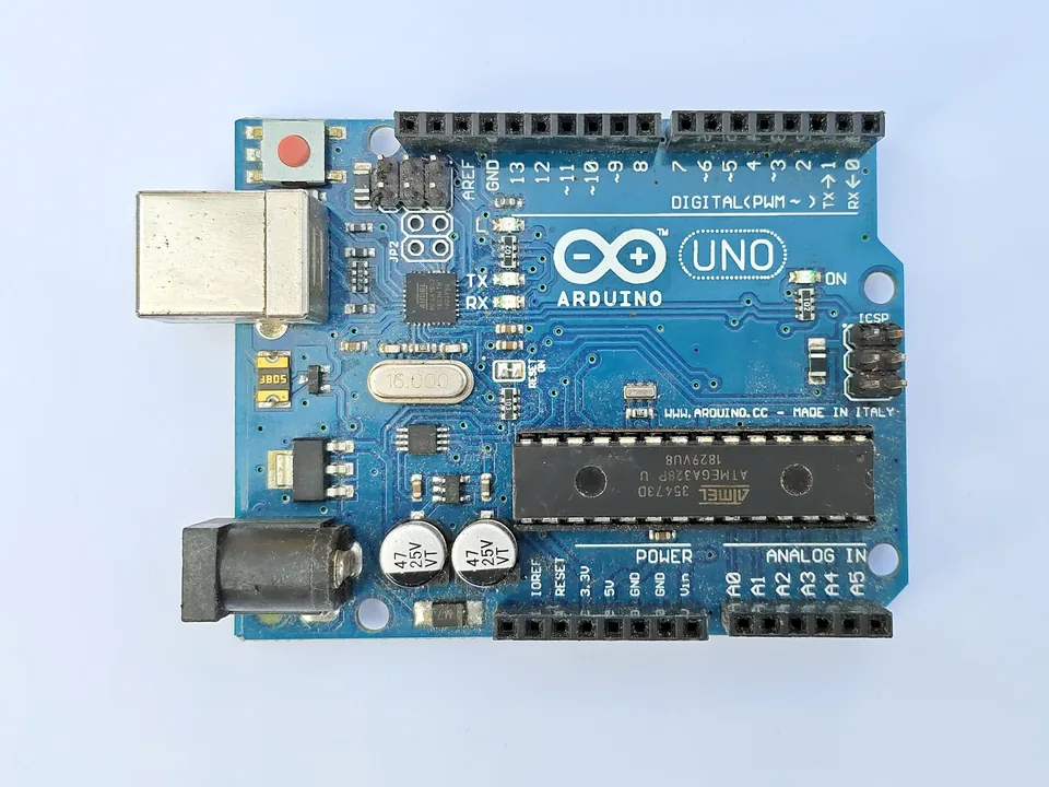

Key specs
- Logic level
- 5 V Evidence: Documented
- MCU
- ATmega328P Evidence: Documented
- Flash
- 32 KB Evidence: Documented
- SRAM
- 2 KB Evidence: Documented
- Digital IO pins
- 14 Evidence: Documented
Works with and related
-

-
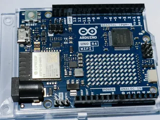
Alternative to
Arduino UNO R4 WiFi
Evidence: Inferred
Datasheet lists UNO R4 Minima/WiFi under Related Products; alternative/successor reading is our inference
Comparisons
Read the caveats · 1 source conflict
Suggested for: Compare boards: documented capabilities
All specifications 11
| Spec | Value | Evidence |
|---|---|---|
| MCU | ATmega328P | Evidence: Documented |
| CPU clock max | 16 MHz 16 MHz ceramic resonator (see conflicts[]) Source conflict (clock): 16 MHz (ceramic resonator) vs up to 20 MHz (ATmega328P CPU) – Board clock is 16 MHz per product page; datasheet 3.2 says up to 20 MHz, likely the MCU rating not the board. Our reading is inference. Audit: datasheet Features (p.2) also says 'AVR CPU at up to 16 MHz', so the datasheet is internally inconsistent; only section 3.2 says up to 20 MHz (ATmega328P rating). Board part Y1 is listed as ECS-160-20-4X-DU 'Oscillator' while the product page says 'ceramic resonator' (part-number decoding to 16 MHz is our unverified inference). Spec clock=16 MHz kept at class 1; conflict left open. RESOLVED 2026-10-18: Microchip DS40002061B rates the ATmega328P 0-20 MHz at 4.5-5.5 V (chip rating); board clock is 16 MHz (product page, datasheet Features). Chip maximum vs board clock are different quantities; datasheet 3.2 restates the chip rating. Residual unverified: Y1 part-number decoding. | Evidence: Documented |
| Flash | 32 KB | Evidence: Documented |
| SRAM | 2 KB | Evidence: Documented |
| Eeprom | 1 KB | Evidence: Documented |
| Digital IO pins | 14 of which 6 PWM | Evidence: Documented |
| Analog inputs | 6 | Evidence: Documented |
| Input voltage max | 20 V VIN pad 6-20 V per datasheet table 2.2 | Evidence: Documented |
| Input voltage min | 6 V VIN pad 6-20 V per datasheet table 2.2 | Evidence: Documented |
| Operating voltage | 5 V Board logic/power rail is 5 V (IOREF connected to 5V; +5V rail); datasheet has no row literally labelled operating voltage - reading is an inference | Evidence: Documented |
| USB connector | USB-B | Evidence: Documented |
Caveats
logic_level_v=5 is supported by datasheet 5.1 JANALOG pin 2: 'IOREF - Reference for digital logic V - connected to 5V' (upgraded to class 1 by audit; previously class 2 inference from the regulator and ATmega328P rating). The datasheet power table does not give a maximum power consumption figure (the cell reads 'xx'). VIN 6-20 V is labelled 'Maximum input voltage from VIN pad' in datasheet 2.2, not a recommended operating range. Clock: board 16 MHz vs ATmega328P rating 20 MHz (resolved 2026-10-18, see conflicts[]).
Claims 4
UNO R3 is based on the ATmega328P with 14 digital I/O pins (6 PWM) and 6 analog inputs. Evidence: Documented
Source: src-arduino-uno-r3-docs
The ATmega328P is replaceable (not soldered). Evidence: Documented
Source: src-arduino-uno-r3-docs
Offline programming uses the Arduino Desktop IDE over a USB-B cable. Evidence: Documented
Source: src-arduino-uno-r3-datasheet
UNO R3 is a 5 V logic board. Evidence: Documented
Source: src-arduino-uno-r3-datasheet
Sources 4
-
Arduino · manufacturer_docs
https://docs.arduino.cc/hardware/uno-rev3/
Locator: Product page, intro paragraph + 'EEPROM'/'Replaceable chip' sections · Retrieved 2026-10-16
Arduino UNO is a microcontroller board based on the ATmega328P. It has 14 digital input/output pins (of which 6 can be used as PWM outputs), 6 analog inputs, a 16 MHz ceramic resonator
-
Arduino · datasheet
https://docs.arduino.cc/resources/datasheets/A000066-datasheet.pdf
Locator: Features p.2; 1.2 Related Products p.5; 2.2 Power Consumption p.6; 3.2 Processor p.7; 4.1 p.9 · Retrieved 2026-10-16
AVR CPU at up to 16 MHz / 32 kB Flash / 2 kB SRAM / 1 kB EEPROM
-
Microchip · datasheet
Locator: Features, Speed Grade · Retrieved 2026-10-18
0 - 4MHz@1.8 - 5.5V, 0 - 10MHz@2.7 - 5.5.V, 0 - 20MHz @ 4.5 - 5.5V
-
Arduino · datasheet
https://docs.arduino.cc/resources/datasheets/A000066-datasheet.pdf
Locator: Section 3 Functional Overview p.7 (USB-B); pin table row 2 IOREF and row 5 +5V · Retrieved 2026-10-18
you'll need a USB-B cable. This also provides power to the board | IOREF Reference for digital logic V - connected to 5V | +5V Power Rail